Common Types of Machine Parts and Methods of Dimensioning
The processing size of machine basic parts is an important standard for inspecting the quality of parts, which will affect the normal operation of the machine. Different types of machine parts have different characteristics and different methods of dimensioning. The following are the common types of machine parts and the method of dimensioning.
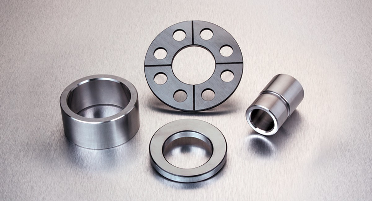
Shaft parts
Such parts generally include shafts, bushings, and other parts. When expressing the views, as long as you draw a basic view and add appropriate cross-sectional views and dimensions, you can express its main shape features and local structure. In order to facilitate the viewing of the picture during processing, the axis is generally placed horizontally for projection, and it is best to choose the position where the axis is the lateral vertical line.
When marking the size of bushing parts, its axis is often used as the benchmark for radial dimensions. From this, the Ф14 and Ф11 shown in the figure (see A-A section), etc. are noted. In this way, the design requirements and the process reference during processing (when the shaft parts are processed on the lathe, the center hole of the shaft is held by the thimble at both ends) are unified. The length direction datum often chooses important end faces, contact faces (shoulders), or machined faces.
Disc cover parts
The basic shape of this kind of part is a flat disc, generally including end caps, valve caps, gears, and other parts. Their main structure is basically a rotating body, usually with various shapes of flanges and uniformly distributed circular holes. And ribs and other local structures. When selecting a view, generally select the cross-sectional view of the symmetry plane or the axis of rotation as the front view, and also need to add other appropriate views (such as left view, right view, or top view) to express the shape and uniform structure of the part.
When marking the size of disc cover parts, the axis through the shaft hole is usually selected as the radial dimension reference, and the main dimension reference in the length direction is often the important end face.
Fork frame parts
Such parts of the machine generally include forks, connecting rods, supports, and other parts. Because their processing positions are changeable, when choosing the main view, the main consideration is the working position and shape characteristics. For the selection of other views, two or more basic views are often required, and appropriate partial views must be used.
When marking the size of the fork frame parts, the installation base surface or the symmetry plane of the part is usually selected as the size reference.
Box parts
Generally speaking, the shape and structure of this type of machine parts are more complex than the previous three types of parts, and the processing position changes more. Such parts generally include the valve body, pump body, reducer box, and other parts. When choosing the main view, the working position and shape characteristics are mainly considered. When selecting other views, appropriate sectional views, cross-sections, partial views, and oblique views should be adopted according to the actual situation to clearly express the internal and external structure of the part.
In terms of dimensions, the axis, important installation surface, contact surface (or processing surface), and symmetry plane (width, length) of some main structures of the box body is usually selected as the size benchmark. For the parts on the box that needs to be cut, the dimensions should be marked as far as possible to facilitate processing and inspection.
Marking the dimensions of machine parts can eliminate unqualified machine parts and ensure their quality and accuracy. If you want to know more about precious machine parts after reviewing the above content, you can contact us for more detailed information and solutions.
As a professional parts manufacturer, we are always committed to providing customers with quality products. We have an experienced R&D department and a professional quality management team, which can conduct a comprehensive inspection of the quality and accuracy of the products. We can also provide thoughtful services and effective solutions according to customer needs. If you are interested in our machine parts, please contact us immediately!